Integrated backflow preventer
The Integrated Backflow Preventer is a reduced pressure zone (RPZ) backflow prevention device featuring a one‑piece cast body that integrates two independent check valves and an intermediate relief chamber. It is specifically designed to prevent toxic, hazardous, or highly contaminated media from flowing back into the upstream potable water supply.
Category:Backflow preventer
Tags:
Call Us Anytime
15669818867
Product
Contact us
- No. 3, Tiandeng Road, Caiqiao Village, Jiangbei Street, Yongjia County, Zhejiang Province
- 15669818867
- Mr JIANG
- 812921123@qq.com
I. Product Overview
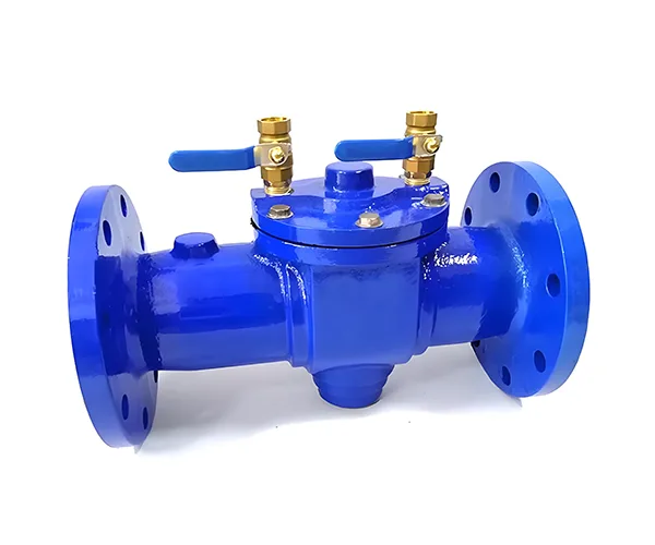
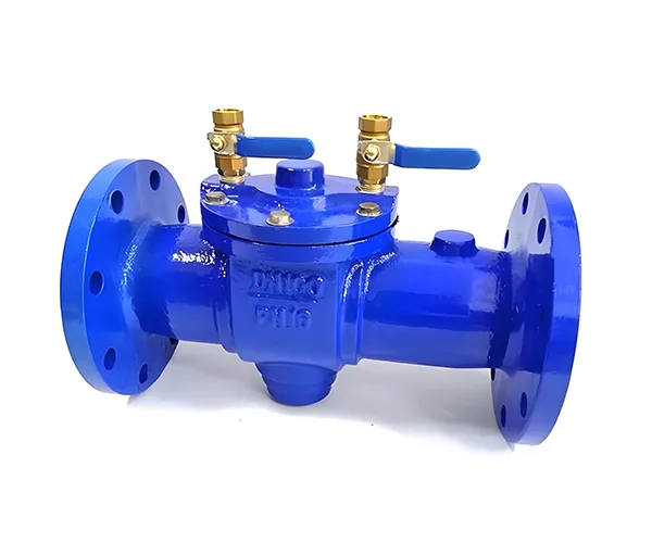
The Integrated Backflow Preventer is a reduced pressure zone (RPZ) backflow prevention device featuring a one‑piece cast body that integrates two independent check valves and an intermediate relief chamber. It is specifically designed to prevent toxic, hazardous, or highly contaminated media from flowing back into the upstream potable water supply. Compared with sectional backflow preventers (assembled from multiple bodies with flanges), the one‑piece design eliminates intermediate flange sealing faces, removing potential external leakage paths, offering a more compact structure, simpler installation, and higher reliability.
This device provides the highest level of backflow protection (conforming to EN 1717 AA level and ASSE 1013). Under any backpressure or backsiphonage condition, it automatically discharges reverse water to the atmosphere. The product features flanged connections and a minimum nominal diameter of DN50. Body materials include ductile iron, stainless steel, or carbon steel. It is widely used in medium to large bore pipelines (DN50–DN300) for municipal water supply, industrial recirculating water, chemical, food, and pharmaceutical applications.
Product Structure
The Integrated Backflow Preventer (RPZ type, flanged) mainly consists of the following parts:
-
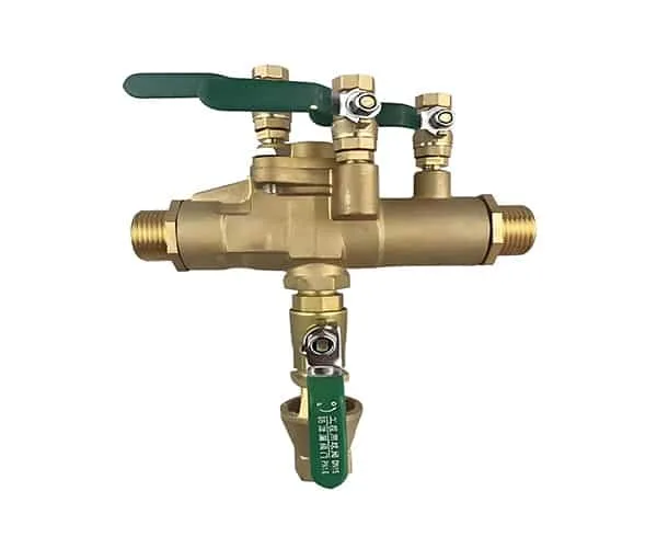
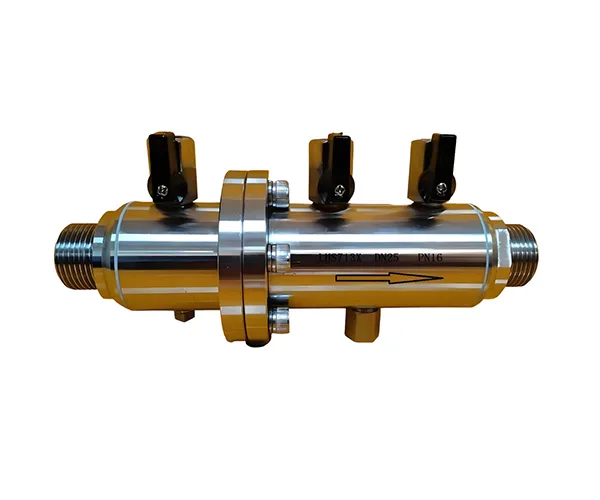
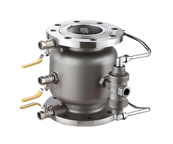
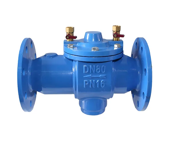
Body: One‑piece precision cast body with no welded seams and no intermediate flange connections. Materials: ductile iron (QT450‑10), stainless steel (CF8/CF8M), or carbon steel (WCB). Flanged ends conforming to GB/T 9113, ANSI B16.5, EN 1092‑1, etc.
-
First Check Valve (inlet side): Spring‑loaded lift check valve with a rubber soft seal (NBR/EPDM/FKM), allowing forward flow.
-
Second Check Valve (outlet side): Same construction as the first, providing dual sealing redundancy.
-
Intermediate Relief Chamber: Located between the two check valves, incorporating a relief valve.
-
Relief Valve: Spring‑loaded differential pressure control valve that automatically opens when the intermediate chamber pressure exceeds the inlet pressure by a set value (typically 0.14 bar), discharging reverse water to atmosphere.
-
Test Cocks: Test ports at the inlet, outlet, and intermediate chamber (typically 3–4 ports, brass or stainless steel) for field verification of each check valve and the relief valve.
-
Drain Connection: Outlet of the relief valve, flanged or threaded, for connecting a drain pipe.
-
Integrated Bonnet: Cast integrally with the body or bolted, allowing easy maintenance.
All internal components can be accessed from the bonnet side without removing the body. The one‑piece construction eliminates intermediate flange gaskets, preventing external leakage.
Function
-
Prevents Backpressure Backflow: When outlet pressure exceeds inlet pressure (backpressure condition), both check valves close, the intermediate chamber pressure rises, the relief valve opens, and any potential leakage is discharged to atmosphere, preventing contamination from entering the upstream.
-
Prevents Backsiphonage: When upstream supply pressure drops sharply (e.g., pipe burst) creating negative pressure, the relief valve in the intermediate chamber draws in air or discharges water, preventing downstream sewage from being siphoned back upstream.
-
Dual Sealing Redundancy: Two independent check valves provide redundant sealing. Even if one check valve slightly leaks, the relief valve in the intermediate chamber will activate, ensuring absolute upstream water safety.
-
Visual/Audible Discharge Indication: Relief valve discharge is usually visible or audible, indicating abnormal conditions.
-
One‑Piece High Reliability: The integrally cast body has no intermediate flange sealing faces, eliminating external leakage risks and ensuring long‑term continuous operation with reduced maintenance frequency.
-
In‑Line Test Capability: The sealing integrity of each check valve and the relief valve set pressure can be tested using the test cocks without removing the valve from the pipeline.
Working Conditions
-
Applicable Media: Drinking water, industrial water, cooling water, fire protection water, lightly contaminated water, chemical media (stainless steel body required), food and pharmaceutical water (sanitary polished finish required), etc.
-
Temperature Range: 0°C to +80°C (standard EPDM seals); –20°C to +120°C (FKM seals).
-
Pressure Rating: PN10, PN16, PN25 (Class 125, Class 150, Class 300).
-
Nominal Diameter: DN50 – DN300 (2″ – 12″); common sizes DN50–DN200.
-
Installation Position: Horizontal pipeline (drain port facing downward); not to be installed upside down.
-
Typical Applications:
-
Connection points between municipal water mains and customer branch lines (preventing customer side backflow)
-
Main water inlets of industrial plants (preventing process water backflow to municipal mains)
-
Chemical plant makeup water lines (stainless steel body for corrosive media)
-
Food & beverage plant water inlets (sanitary stainless steel body)
-
Pharmaceutical purified water system inlet ends
-
Fire protection tank fill lines (preventing fire water backflow)
-
Boiler house soft water makeup systems
-
Summary
The Integrated Backflow Preventer (RPZ type, flanged), with its one‑piece cast body, dual check valve plus relief chamber redundant design, highest level of backflow protection, and in‑line test capability, is the preferred safety device for preventing high‑hazard backflow in medium to large bore pipelines (DN50 and above). Compared with sectional backflow preventers, the one‑piece design eliminates intermediate flange sealing faces, removes external leakage risks, offers simpler installation, and provides higher reliability.
The product is available in ductile iron, stainless steel, or carbon steel bodies to suit municipal, industrial, chemical, food, and pharmaceutical applications. For pipeline systems that demand the highest backflow prevention level and long‑term maintenance‑free operation, the Integrated Backflow Preventer is an indispensable core safety component.
| Parameter | Value Range |
|---|---|
| Nominal Diameter (DN) | DN50 – DN300 (2″ – 12″) |
| Nominal Pressure (PN) | PN10, PN16, PN25 (Class 125, Class 150, Class 300) |
| Applicable Temperature | 0°C to +80°C (standard); –20°C to +120°C (FKM seals) |
| Body Material | Ductile iron (QT450‑10), stainless steel (CF8/CF8M), carbon steel (WCB) |
| Check Valve Cartridge Material | Stainless steel + NBR/EPDM/FKM seal |
| Spring Material | Stainless steel 304 or 316 |
| Seal Material | EPDM (standard), NBR (oil service), FKM (high temperature/chemicals) |
| Relief Valve Set Pressure | Typically 0.14 bar (2 psi) differential pressure trigger |
| Connection Type | Flanged (GB/T 9113, ANSI B16.5, EN 1092‑1) |
| Body Construction | One‑piece cast body |
| Max. Working Pressure | 1.0 / 1.6 / 2.5 MPa (depending on model) |
| Test Ports | 3–4 standard test cocks (inlet, outlet, intermediate chamber) |
| Drain Connection | Flanged or threaded |
| Applicable Standards | EN 1717 (AA level), ASSE 1013, AWWA C511, GB/T 25178 |