Automatische ontluchtingsklep
Bovenop HVAC-leidingen, zonne-energiesystemen, opslagtanks en industriële apparatuur treft u vaak een klein messing of roestvrijstalen ventiel aan. Het vereist geen handmatige bediening, maar laat toch stil en automatisch lucht uit het systeem ontsnappen. Dit is een compacte automatische ontluchtingsklep (ook wel automatische luchtafvoerklep genoemd). Dit artikel richt zich op float-type automatische ontluchtingskleppen met een diameter van DN15 tot DN32, waarvan de behuizing is gemaakt van messing of roestvrij staal, en biedt een systematische uitleg van hun werkingsprincipe, constructiematerialen, installatiemethoden en toepassingsscenario's.
Category:Luchtklep
Call Us Anytime
15669818867
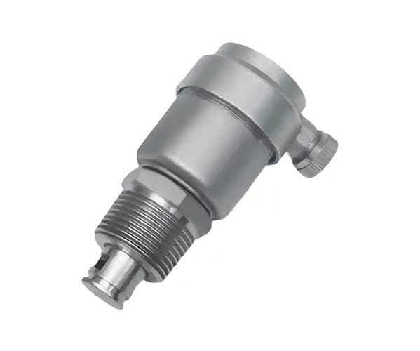
Compact Automatic Air Vent Valve: Brass and Stainless Steel, DN15–DN32 for HVAC and Equipment Venting
On top of HVAC piping, solar thermal systems, storage tanks, and industrial equipment, you can often spot a small brass or stainless kraan. It requires no manual operation, yet quietly and automatically expels air from the system. This is a compact automatic air vent valve (also called an automatic air release valve). This article focuses on float-type automatic air vent valves ranging from DN15 to DN32, with bodies made of brass or stainless steel, providing a systematic explanation of their working principle, construction materials, installation methods, and application scenarios.
What Is a Compact Automatic Air Vent Valve?
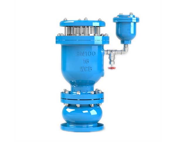
A compact automatic air vent valve is a purely mechanical air release device that operates on the buoyancy principle—”closed when water is present, open when air is present.” It differs from manual air vents that require hand-operated unscrewing to release air, and it also differs from the large air/vacuum valves used on large pipelines for rapid filling and draining. Its core mission is: during pressurized system operation, to continuously and automatically release trace amounts of gas that come out of solution from the liquid, preventing air locks, and to close automatically and tightly once the air is expelled, preventing water leakage.
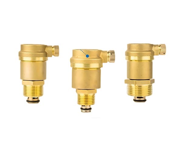
Working Principle: Automatic Float Action Inside a Miniature Valve Chamber
Despite the small size, the internal structure is precise and robust:
-
Body and Bonnet: Hot-forged or cast brass body housing the float and sealing mechanism.
-
Float (Float Ball): A hollow float ball typically made of PP or high-temperature-resistant plastic, with a density far lower than water.
-
Lever Mechanism: Connects the float to the sealing face on the underside of the bonnet; the float rising and falling opens and closes the vent orifice.
-
Vent Orifice: Located at the top of the bonnet, very small in diameter (typically only 1–3 mm), ensuring that under system pressure only gas is vented and no water is sprayed.
Operating Cycle:
-
When air from the system enters the valve chamber from a high point in the piping, the water level is pushed down by the gas. The float descends with the water level, actuating the lever to open the top vent orifice.
-
Air is discharged through the vent orifice as system pressure continuously forces gas toward the valve chamber.
-
Once the air is fully expelled, water refills the valve chamber. The float rises due to buoyancy, and the lever pushes the sealing gasket tightly against the orifice to close it.
-
The vent orifice is typically fitted with a dust cap/protective cover to prevent external dust ingress; it can also be manually unscrewed to perform a venting test.
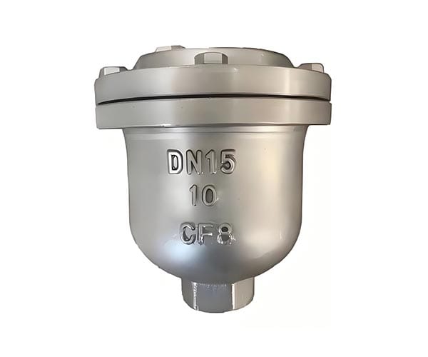
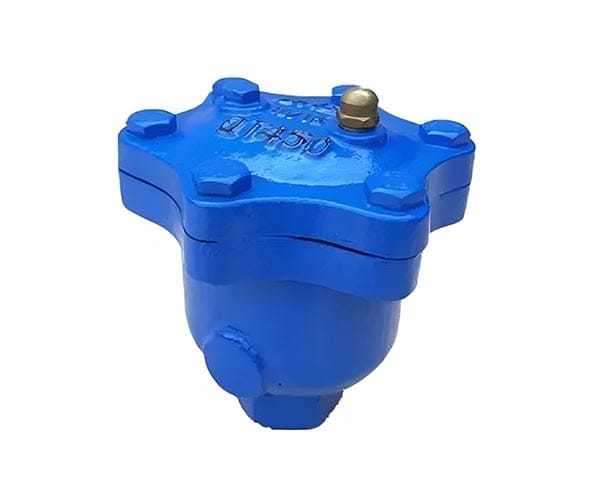
Material Selection: Brass vs. Stainless Steel
| Meerdere omwentelingen (rijzende spindel) | Brass | Roestvrij staal |
|---|---|---|
| Material Grade | HPb57-3, CW617N | 304, 316 |
| Geschikte Media | Water, glycol solutions, low-corrosivity liquids | Water, weak acids and alkalis, food-grade media, high-temperature fluids |
| Temperature Limit | ~120°C | ~180°C (verify seal rating for higher temperatures) |
| Corrosiebestendigheid | Good resistance to water corrosion; avoid ammonia and strong acid environments | Superior corrosion resistance, especially 316 in chloride-containing environments |
| Toepassingen | HVAC heating, solar thermal, compressed air systems | Food, chemical, high-temperature hot water, steam systems (with metal seals) |
| Kosten | Lower | Higher |
Selection Recommendation: For general building heating and domestic hot water systems, the economical brass type is preferred. For applications with high sanitary requirements, chlorine exposure, corrosive environments, or high-temperature steam systems, select the stainless steel type.
Common Installation Locations
Compact automatic air vent valves are typically installed at the highest point of the system or wherever air is most likely to collect:
-
Radiator/towel warmer ends: Replace manual air vents with automatic air vents to eliminate repeated manual bleeding.
-
Top of manifolds and headers: Critical air removal points in HVAC systems.
-
Top of boilers/storage tanks: Expel dissolved gases released during heating.
-
Highest point of solar collectors: Prevent air locks that can cause circulation stagnation.
-
Top of compressed air receiver tanks: Automatically discharge condensate and oil mist entrained in the air.
-
High points of industrial equipment cooling circuits: Ensure smooth coolant circulation.
Installation Considerations
-
Install vertically, vent port facing upward: De vlotter moet in lijn met de zwaartekracht bewegen. Een schuine installatie zorgt ervoor dat de vlotter vastloopt.
-
Gebruik afdichtingsmaterialen op verbindingen: Gebruik PTFE-tape of schroefdraadpasta op schroefdraadverbindingen om lekkage te voorkomen. Zorg ervoor dat er geen afdichtingstape in het inwendige van het kleplichaam terechtkomt.
-
Installeer een afsluitklep: Installeer een kleine afsluitklep (zoals een mini-kogelkraan) stroomopwaarts van de ontluchtingsklep om onderhoud of vervanging mogelijk te maken zonder het gehele systeem te hoeven aftappen.
-
Beheer van afvoeropening: Het ontluchtingsproces kan gepaard gaan met zeer kleine hoeveelheden waterspray. De stofkap kan worden vastgeschroefd zodat druppels langs het kleplichaam kunnen weglopen, of er kan een afvoerslang worden aangesloten.
-
Vorstbescherming: Indien geïnstalleerd buitenshuis of op locaties die aan vorst kunnen worden blootgesteld, kies dan een model met thermische isolatie of een vorstbestendig ontwerp om te voorkomen dat het kleplichaam barst bij lage temperaturen.
Selectiechecklist
-
Bevestig de vereiste diameter (DN15/20/25/32) en schroefdraadstandaard (BSP of NPT)
-
Controleer of de mediumtemperatuur en -druk binnen het nominale bereik van de klep vallen
-
Als het medium olie of chemicaliën bevat, kies dan een geschikt afdichtingsmateriaal (bijv. FKM)
-
Bepaal of een handmatige ontluchtingstestknop of stofkap vereist is
-
Zorg voor voldoende installatieruimte (kleplichaamhoogte varieert doorgaans tussen 60–120 mm)
Veelvoorkomende problemen en probleemoplossing
| Symptoom | Mogelijke oorzaak | Corrigerende maatregel |
|---|---|---|
| Continue waterlekkage/druppels uit ontluchtingsopening | Versleten afdichtingsoppervlak, vastzittend vreemd deeltje, beschadigde vlotter | Sluit de stroomopwaartse afsluitklep, demonteer, reinig of vervang de afdichtingspakking/vlotter |
| Luchtinsluiting blijft bestaan maar klep ontlucht niet | Ontluchtingsopening geblokkeerd (kalkaanslag, vuil), vlotter vastgelopen | Demonteer, inspecteer en reinig; installeer een zeef stroomopwaarts |
| Overmatige waterspray tijdens ontluchting | Hoge systeemdrukfluctuatie, of geselecteerde openingsgrootte te groot | Installeer een dempingsring, of controleer opnieuw of de modelkeuze geschikt is |
Samenvatting:
De compacte automatische ontluchtingsklep is een van de meest onopvallende maar toch kritisch belangrijke beschermingscomponenten in HVAC-, warmwater-, zonne-energie- en industriële apparatuursystemen. Met een puur mechanisch drijfvermogenprincipe beschermt het continu het systeem tegen luchtinsluitingen. Het correct kiezen tussen messing en roestvrij staal, het afstemmen van de juiste installatiepositie en het volgen van standaardpraktijken zorgen voor een soepele systeemcirculatie, verbeterde efficiëntie en vrijheid van het gedoe van herhaaldelijk handmatig ontluchten.