Low resistance backflow preventer
저저항 역류방지기는 역류를 방지하고 급수 시스템을 오염으로부터 보호하면서 압력 손실을 최소화하도록 설계된 고효율 장치입니다. 최적화된 유로와 첨단 밀봉 기술을 갖춘 이 역류방지기는 음용수, 소방 및 산업 시스템에서 안정적인 작동과 에너지 효율성을 보장합니다. 스테인리스강, 청동 또는 연성철로 제작된 이 밸브는 내구성과 내식성이 뛰어나며, 높은 유량과 낮은 유지보수가 요구되는 용도에 적합합니다. 저저항 설계는 에너지 소비를 줄여 압력 손실이 중요한 문제인 시스템에 이상적인 선택입니다.
Category:역류 방지기
Call Us Anytime
15669818867
Product Overview

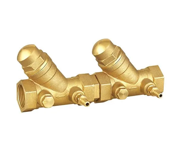
1. Normal operating condition: When the upstream pressure is higher than the downstream pressure, and the upstream and downstream check valves are operating normally, no water will drain from the bottom.
2. Ultra-high downstream pressure: When the downstream pressure is higher than the upstream pressure, the upstream and downstream check valves are closed, and water is drained from the bottom.
3. Damage to downstream check valve: When the downstream pressure is higher than the upstream pressure, the downstream and upstream check valves are closed, preventing water from draining from the bottom and entering the upstream.
4. Damage to upstream check valve: When the downstream pressure is higher than the upstream pressure, the upstream check valve is in a leaking state and the water drains from the bottom, preventing water from entering the upstream.
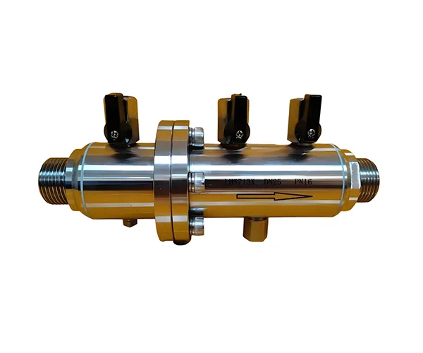
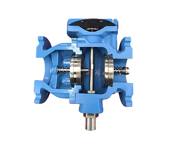
The product adopts a diaphragm-type hydraulic control structure on the top, forming triple safety protection together with dual check units. It is widely used in connection nodes of municipal water supply networks, building secondary water supply, fire water supply systems, as well as different water quality systems such as domestic drinking water, reclaimed water, fire water and greening water, serving as key equipment for water supply safety protection.

Core Structure
- Top Diaphragm-Type Hydraulic Control Unit
As the core sensing and control component, it uses a flexible diaphragm as the pressure difference sensing element to monitor the pressure changes of the inlet, outlet and intermediate cavity in real time. There is no mechanical transmission friction, so it acts sensitively and reliably, is not affected by fine impurities in the medium, and has no risk of jamming during long-term operation.
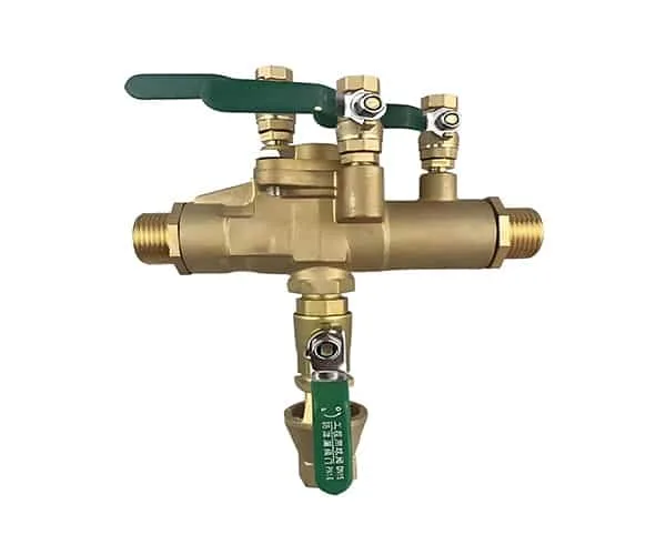
- Inlet Check Unit
With a spring-assisted elastic sealing structure, it realizes primary one-way cut-off, features low opening resistance and fast reverse closing response, and reduces head loss during normal water supply.
- Outlet Check Unit
An independent secondary check sealing structure, forming dual check redundant protection with the inlet unit. It can effectively block the backflow path even if a single-stage seal fails.
- Intermediate Cavity and Drainage Unit
Located between the two-stage check units, it is linked and controlled with the top diaphragm-type unit. Under abnormal working conditions, it can automatically drain water and form an air partition to completely cut off the backflow channel.
Working Principle (With Diaphragm Structure)
1 Normal Water Supply Condition
2 Abnormal Backflow Condition
- Backpressure Backflow (Outlet Pressure > Inlet Pressure): The diaphragm-type unit quickly senses the reverse pressure difference, drives the drain valve to open instantly, and the two-stage check units close synchronously. The medium in the intermediate cavity is discharged and air is introduced to form a partition, blocking the backflow path.
- Siphon Backflow (Inlet Pressure Sudden Drop / Negative Pressure): The diaphragm-type unit senses the loss of inlet pressure, the drain valve is fully opened, and a large amount of air enters the valve cavity to destroy the siphon effect, preventing the polluted medium downstream from flowing back to the upstream clean pipe network.
3 Micro-Leakage Protection
Core Advantages
- Diaphragm Control, Sensitive & Wear-Free
The top diaphragm-type hydraulic control structure has no mechanical transmission friction and fast response speed, and is not affected by medium impurities. Compared with traditional mechanical control structures, it greatly improves long-term operation reliability and extends the maintenance cycle.
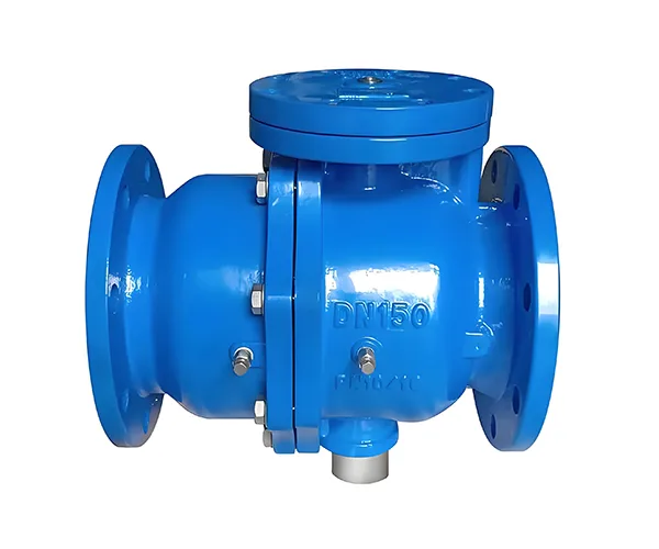
- Full Size Range, Strong Adaptability
Covering DN50~DN300, it can meet different flow demands from branch pipes to main pipes, and is suitable for municipal, construction and industrial scenarios.
- Ultra-Low Flow Resistance, Energy-Saving & Efficient
The optimized wide flow channel design greatly reduces the flow resistance of the medium, cuts down the energy consumption of pump units and operating costs of the water supply system, especially suitable for long-term use of large-flow water supply systems.
- Dual Check Redundant Protection, High Safety Level
Triple protection of two independent check units plus diaphragm-linked drainage, with no shared mechanical parts, avoiding overall failure caused by a single point fault, meeting the requirements of high-safety water supply scenarios.
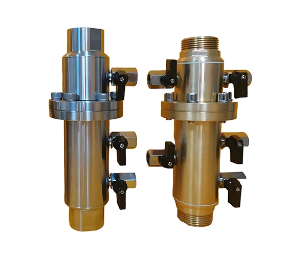
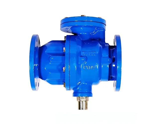
- Easy Installation & Maintenance
Compact structure with short installation length saves on-site space; supports horizontal / vertical installation, equipped with online detection interface, allowing drainage function testing without water shutdown, and no overall disassembly required for daily maintenance.
Installation & Operation Instructions
- Pre-Installation Preparation: Thoroughly flush the pipeline to remove welding slag, rust and other impurities to avoid jamming the diaphragm or check units; reserve maintenance space at the installation location for later maintenance.
- Installation Requirements: Prioritize installation on horizontal pipelines, with the flow direction arrow on the valve body consistent with the medium flow direction; install maintenance gate valves at both ends of the valve, and a filter is recommended at the inlet end to prevent impurities from entering the valve and affecting diaphragm performance.
- Drain Outlet Treatment: The drain outlet must be connected to open drainage facilities (such as floor drains, drainage ditches), and shall not be directly connected to closed drainage pipelines to avoid backpressure affecting the drainage function.
- Commissioning Steps: Close the outlet gate valve, slowly open the inlet gate valve to fill the valve with water and exhaust air, then slowly open the outlet gate valve to avoid water hammer damage to the diaphragm or check components.
- Daily Maintenance: It is recommended to test the linkage performance of the diaphragm-type unit and drain valve and check the status of the diaphragm and seals every six months; in case of slow action or leakage, clean impurities and replace aged diaphragms in time to restore use.
Typical Application Scenarios
- Connection nodes between municipal water supply networks and user branch pipes
- Matching installation for secondary water supply equipment (non-negative pressure water supply, variable frequency water supply)
- Fire water supply and central air conditioning circulating water systems
- Places with high requirements for water quality safety such as hospitals, food processing plants and natatoriums
- Cross-connection points of industrial circulating water and sewage systems to prevent medium pollution and backflow