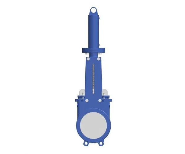
Hydraulic Knife Gate Valve
The Hydraulic Knife Gate Valve is a knife‑edge gate valve driven by a hydraulic actuator. It is designed only for ON‑OFF (open/close) service – not for flow regulation. Compared with manual, electric, or pneumatic knife gate valves, the hydraulic version offers high thrust, fast response, remote hydraulic control, and excellent explosion‑proof performance. It is particularly suitable for large diameters, high operating pressures, frequent cycling, and hazardous (explosive) environments.
Category:Knife gate valve
Tags:
Call Us Anytime
15669818867
Product
Contact us
- No.20 Xueyuan Road, Haidian District, Beijing
- 15669818867
- Mr JIANG
- 812921123@qq.com
Product Overview
The Hydraulic Knife Gate Valve is a knife‑edge gate valve driven by a hydraulic actuator. It is designed only for ON‑OFF (open/close) service – not for flow regulation. Compared with manual, electric, or pneumatic knife gate valves, the hydraulic version offers high thrust, fast response, remote hydraulic control, and excellent explosion‑proof performance. It is particularly suitable for large diameters, high operating pressures, frequent cycling, and hazardous (explosive) environments.
The sharp knife‑edge gate cuts through hanging fibers, paper, plastic strips, and other materials during closure, preventing clogging. The body flow path has no recesses, providing self‑cleaning action. The valve has flanged connections, with nominal diameters from DN100 to DN800, pressure ratings PN10/PN16 (Class 150), and body materials including cast iron, carbon steel, and stainless steel. The hydraulic actuator can be operated with a manual pump or integrated into a hydraulic power unit.
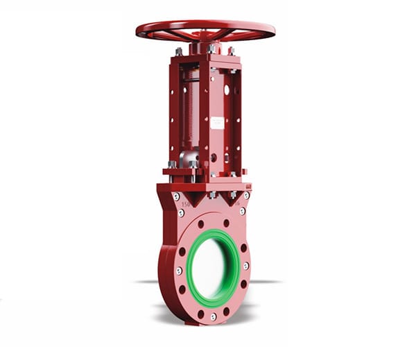
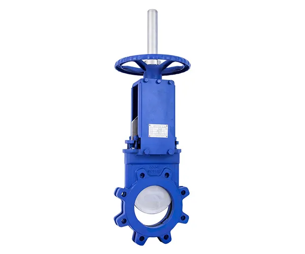
Product Structure
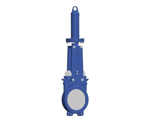
The Hydraulic Knife Gate Valve mainly consists of the hydraulic actuator (ON‑OFF type) and the valve body assembly.
Hydraulic Actuator (ON‑OFF Type):
-
Hydraulic Cylinder: Single‑acting or double‑acting cylinder, with the piston rod connected to the valve stem to raise and lower the gate.
-
Control Valve Group: Includes directional control valve (3/4‑way or 2/4‑way), flow control valve, relief valve, check valve, etc., to control the direction and speed of cylinder movement.
-
Hydraulic Ports: Standard oil inlet/outlet ports (e.g., G1/4″, G3/8″, SAE flange) for connection to a hydraulic power unit or manual pump.
-
Stroke Limit Devices: Adjustable proximity switches or mechanical stops to provide open/closed position feedback.
-
Manual Emergency Device: Some models are equipped with a manual pump or handwheel for operation during hydraulic power unit failure.
-
Enclosure Protection: Cylinder and valve group rated IP65 or higher for harsh environments.
Valve Body Assembly:
-
Body: Cast or fabricated body in gray cast iron, ductile iron, carbon steel (WCB), stainless steel (CF8/CF8M), etc. Flanged ends conforming to GB/T 9113, ANSI B16.5, EN 1092‑1, etc. Full‑bore flow path with no recesses.
-
Gate: Stainless steel (304, 316, 310S) knife‑edge gate with a sharp edge to cut through fibers and particles. The gate surface can be hardfaced with Stellite or chrome‑plated.
-
Seats: Available in rubber (EPDM, NBR, FKM), PTFE, or metal sealing; bidirectional sealing optional.
-
Stem: Stainless steel trapezoidal‑thread stem (or direct‑connected) linked to the hydraulic cylinder piston rod.
-
Packing Box: Contains PTFE or flexible graphite packing, compressed by a packing gland to prevent external leakage.
-
Yoke: Connects the body to the hydraulic cylinder.
The hydraulic actuator provides smooth, adjustable opening/closing speeds. The flow control valve allows the gate speed to be regulated, reducing water hammer or impact.
Function
-
Hydraulic Drive: The hydraulic cylinder delivers high thrust, suitable for large diameters or high‑pressure applications, with smooth operation.
-
Adjustable Speed: The gate speed can be adjusted via the flow control valve to suit different media characteristics and reduce impact.
-
Remote Hydraulic Control: Can be integrated with a hydraulic power unit for remote centralized control without on‑site electricity or compressed air.
-
Explosion‑Proof Performance: The hydraulic system has no electrical components (limit switches can be intrinsically safe or explosion‑proof), making it suitable for flammable/explosive environments.
-
Knife‑Edge Cutting Function: The sharp gate edge cuts through fibers, lumps, and particles during closure, preventing clogging.
-
Self‑Cleaning Flow Path: The recess‑free flow path allows media to flush the interior when fully open, preventing solids accumulation.
-
Bidirectional Sealing (optional): Bidirectional floating seats allow the valve to withstand media pressure from either direction.
-
Full‑Bore Low Flow Resistance: When fully open, the gate is completely out of the flow path, providing minimal pressure loss.
-
Manual Emergency Operation: A manual pump or handwheel option allows valve operation if the hydraulic power unit fails.
Working Conditions
-
Applicable Media: Sewage, sludge, pulp, slurry, tailings, coal slurry, ash slag, mud, particle‑laden liquids, etc.
-
Temperature Range: –20°C to +200°C (PTFE seats); –20°C to +80°C (rubber seats); –29°C to +550°C (metal seats).
-
Pressure Rating: PN10, PN16 (Class 150); higher ratings available on request.
-
Nominal Diameter: DN100 – DN800 (4″ – 32″); larger sizes available on request.
-
Hydraulic System Pressure: Typically 6–16 MPa, depending on actuator size.
-
Hydraulic Medium: Mineral oil, fire‑resistant fluid, water‑glycol (must be compatible with seals).
-
Installation Orientation: Vertical stem‑up recommended.
-
Typical Applications:
-
Underground mine slurry pipelines (high explosion‑proof requirement)
-
Chemical plant slurry shut‑off in hazardous areas
-
Frequent‑operation sludge discharge valves in large wastewater treatment plants
-
Blast furnace slag lines in metallurgy
-
Ash and slag discharge systems in power plants (remote centralized control)
-
Large‑diameter pulp lines in paper mills (high thrust requirement)
-
Offshore platform particle‑laden media pipelines (hydraulic control without electricity/air)
-
Summary
The Hydraulic Knife Gate Valve, with its advantages of hydraulic drive for high thrust, adjustable open/close speed, explosion‑proof performance, and remote control, is an ideal shut‑off valve for large‑diameter, high‑pressure, frequent‑operation, or hazardous environments handling particle‑ or fiber‑laden media. Compared with electric knife gate valves, the hydraulic version is safer in explosive atmospheres and its thrust is not limited by electrical power.
Compared with pneumatic knife gate valves, hydraulic drive provides greater thrust and smoother speed control, especially suitable for high‑viscosity or hard‑particle slurries. With flanged connections, a full‑bore flow path, and optional manual pump or integration with a hydraulic power unit, the Hydraulic Knife Gate Valve is a professional, efficient, and safe solution for ON‑OFF pipeline systems that require reliable shut‑off, handle solids or fibers, and demand explosion protection or high thrust.
| Nominal Diameter (DN) | DN100 – DN800 (4″ – 32″) |
| Nominal Pressure (PN) | PN10, PN16 (Class 150); higher available on request |
| Applicable Temperature | –20°C to +550°C (depending on seat material) |
| Body Material | Gray cast iron, ductile iron, carbon steel (WCB), stainless steel (CF8/CF8M), duplex |
| Gate Material | Stainless steel 304, 316, 310S (optional Stellite hardfacing or chrome plating) |
| Seat Material | EPDM, NBR, FKM, PTFE, metal (Stellite hardfaced) |
| Sealing Construction | Unidirectional (standard) or bidirectional (optional) |
| Packing Material | PTFE, flexible graphite |
| Connection Type | Flanged (GB/T 9113, ANSI B16.5, EN 1092‑1) |
| Drive Type | Hydraulic (single‑acting or double‑acting cylinder) |
| Control Mode | Manual directional valve, solenoid valve (with hydraulic power unit) |
| Hydraulic Pressure | 6–16 MPa (depending on actuator specification) |
| Leakage Class | Soft seal: zero leakage; Metal seal: ANSI Class IV–V |
| Design Standards | T/CFA 0101, MSS SP‑81, reference ISO 4413 (hydraulic) |